Flip-flops are a type of widely used sequential circuit for storage that make use of two gated D-latches. They’re the main component within registers.
Types
Flip-flops can be either level-sensitive (like latches) or edge-triggered. Level-sensitive flip-flops will follow values so long as the clock is at a given value (usually at clock = 1). To expand, what this means is that if the clock is at our chosen value, then the circuit will follow changes in the input. Otherwise it won’t.
Edge-triggered flip-flops respond to the value of the input only when the clock changes from one state to another. Positive edge-triggered circuits trigger when the clock goes from 0 to 1. For negative circuits, this is when the clock goes from 1 to 0.
In the image below, we have a gated D-latch, that are level-sensitive, positive edge-triggered, and negative edge-triggered.
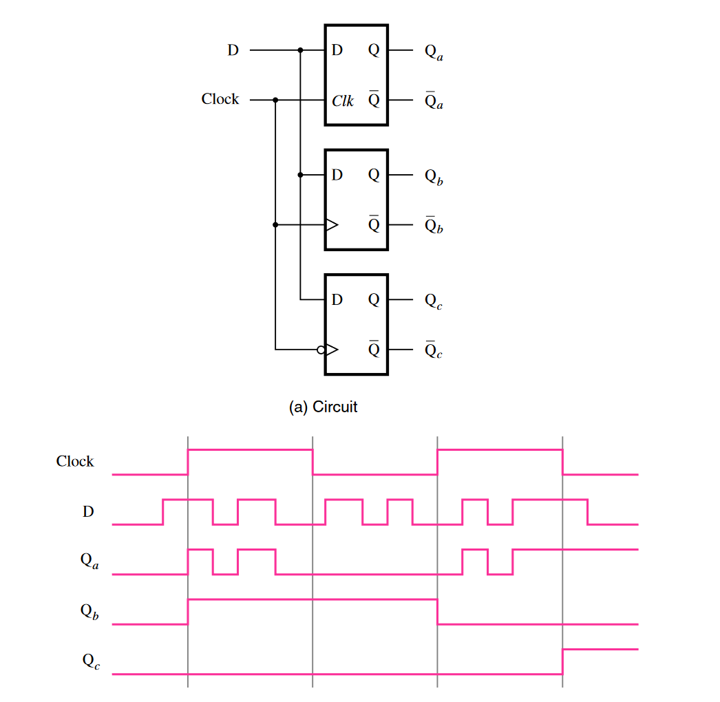
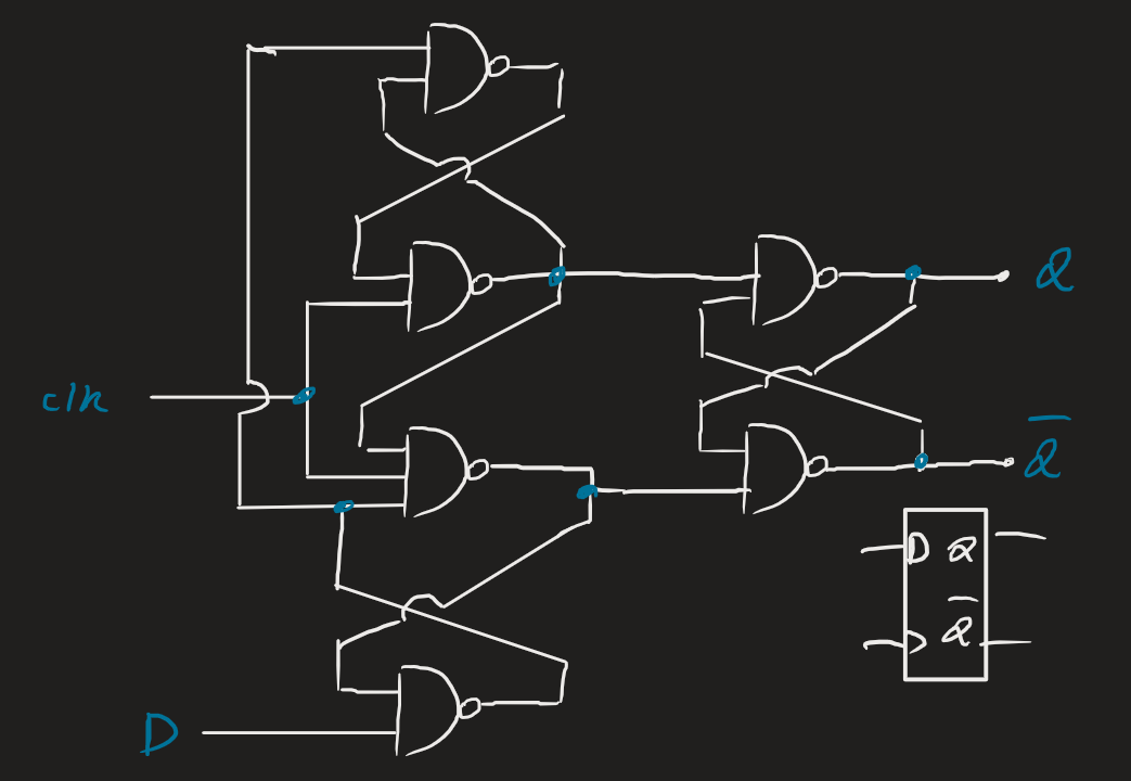
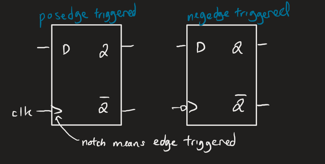 We can implement edge-triggered flip-flops with NAND gates. The below is positive edge-triggered:
Circuit variations
Other than the usual D edge/level-triggered flip-flops, we also have several variations:
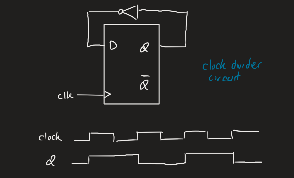
The below is a clock divider, which outputs a signal that’s half the clock speed.
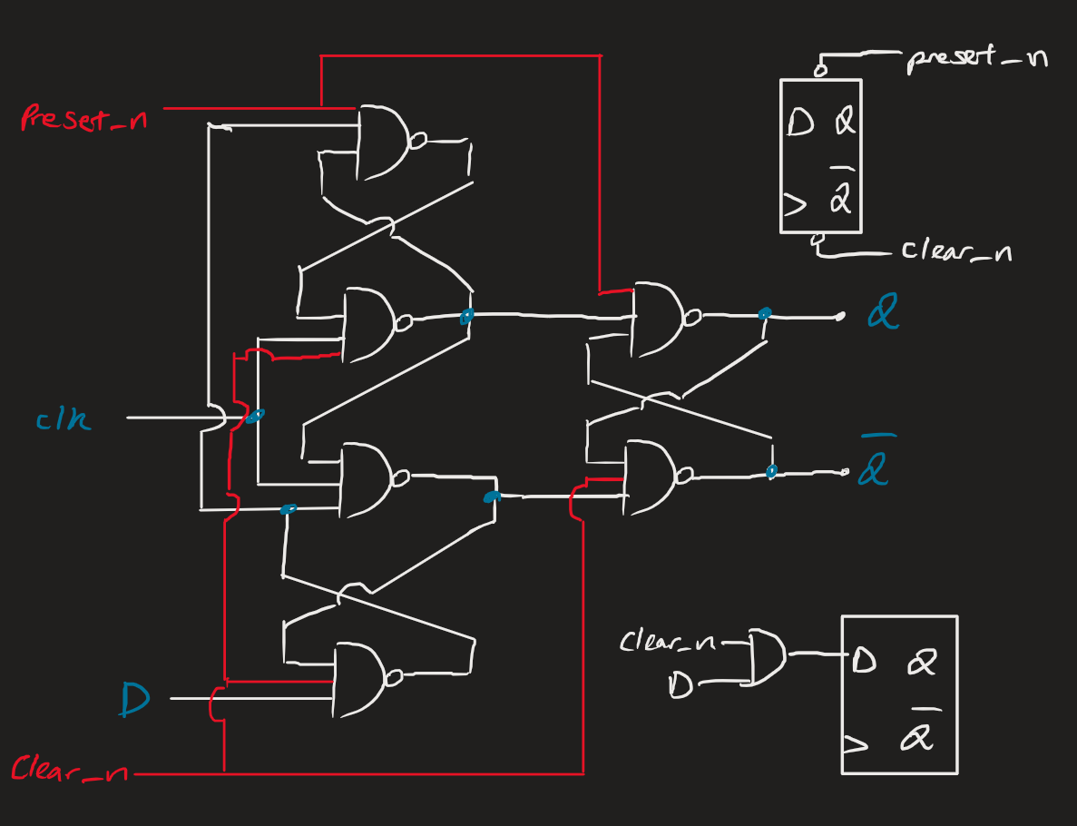
Clear and pre-set
Oftentimes some circuits have a clear and pre-set inputs. They are self-explanatory: they reset or pre-set the inputs at a given time.
By asynchronous RS, we mean we force R to 0 and force S to 1. This is especially useful during circuit start-up, when we want a pre-set starting value and not something unexpected or random.
Verilog implementation
Notice that we use posedge, which refers to the rising edge of the clock. Also note the non-blocking assigment used for Q.
Also see that we don’t have D in the sensitivity list. But we see from above that a change in D doesn’t cause a change in Q, it’s a change in the clock that causes that change.
The Verilog code for a positive edge-triggered flip-flop with active-high synchronous reset is:
module d_flipflop(D, clock, reset, Q);
	input D, clock, reset;
	output reg Q;

	always@(posedge clock)
	begin
		if (reset)
			Q <= 0;
		else
			Q <= D;
	end
endmodule