Nios II is a RISC instruction set architecture for 32-bit embedded processors (specifically for Altera FPGAs), with 32 registers. The DE1-SoC loads Nios II as a soft core processor.
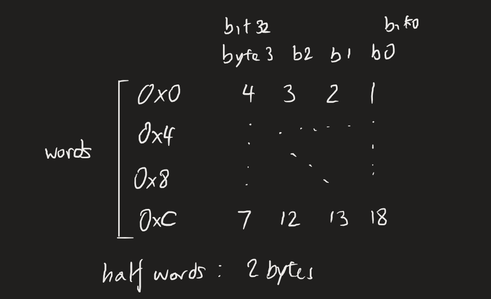
It’s little-endian,1 and has a memory space that supports words, half-words, and bytes. Each separate byte has its own address in memory.
Instructions
Instructions have two basic modes. One is immediate mode, where we use a 16-bit number in our instructions. This is always suffixed by i. The other is register mode, where the values are held in the registers already.
Basic register operations:
- Moving data
mov rX, rYmoves the data ofrYtorX.movi rX, Imm16to “move immediate” a 16-bit number intorX. There will be a sign extension.movhi rX, Imm16to move to the upper 16-bits of the register.movia rX, Imm32, for a 32-bit number. This is a macro, i.e., it is essentially two instructions at once: amovhiof the upper 16 bits then anaddiof the lower 16 bits.
- Loading data, note that this requires the register to already be holding a memory address (via a move instruction).
ldw rX, n(rN), load intorXthe value atrNshifted bynbytes forward.- This is basically pointer arithmetic and dereferencing.
- The preceding instruction should be:
movia rN addr32.- We’re basically loading a 32-bit address into register
N, then when we callldw, we load from the address stored inN. This is due to the restrictions of the architecture, a load-store style. - We can alternatively specify the address for a given word with a directive:
list: .word 10— wherever the assembler chooses to place the memory word with value 10, the “variable”listwill refer to that address.- Variable positions in memory will change! So this makes the most sense to do
- We’re basically loading a 32-bit address into register
- The
wafter theldrefers to loading every 4 bytes.
ldwio rX, n(rN), whererNstores the address of an I/O device.ldh,ldhu,ldwu,ldb,ldbu,lduito specify the contents of the move.umeans unsigned. By default, registers hold signed values. Sign extensions will be with 0.hmeans half-word. A sign extension will be done for the next 16-bits. We can only enter an address ending in 0.bmeans byte. The other bytes are the sign bit.ifor immediate mode.
- Storing data, same address restriction as above
stw rX, n(rN), store into the shifted address atrN, the value atrX.stwio rX, n(rN)
Arithmetic, logic, and bitwise operations:
- Arithmetic operations
add,addisub,subimul,mulu, no immediate variantdiv,divu, no immediate variant
- Logic operations
and,andior,orixor,xori- Note that these operate bit-by-bit. The upper 16 bits are left-alone.
- Bit shifting, where bits are lost and set to 0.
- Logical shift, this is an unsigned shift
srli rX, rY, Imm16;srlsll,slli
- Arithmetic shift, this is a signed shift where the sign bit is duplicated
srai,sra,slai,sla
- Logical shift, this is an unsigned shift
- Bit rotating, note that only the last 5 bits really matter, since registers are only 32-bits
- Rotate right →,
ror,rori - Rotate left ←,
rol,roli
- Rotate right →,
Flow control and functions:
- Branches
br BRANCHto unconditionally enterBRANCH.- For conditional branches, we have the general form
bXX rX, rY, BRANCH:beq, forx == ybne, forx != ybge, for a signed comparisonx >= ybgeu, for an unsigned comparisonx >= yblt, forx < ybgt, forx > y- and so on.
- Subroutines:
call NAMEcalls a subroutineNAME.retreturns from a subroutine. It moves the value ofraintopc, such that the next instruction isra.
- Interrupts:
eretreturns from an interrupt. It moves the value ofeaintopc.rdctlreads control registers.wrctlwrites to control registers.
Directives
A full list here.
.datato specify a section, for variables in memory..align n, to specify the “memory alignment”. This is used when specifying words of data;nwill be the exponent in an offset by .- “align with next available address divisible by ”
.data
.align 2
a: .word 0
b: .word 0x11223344
c: .word 0x55667788.text, to specify instructions..globalto specify global variables..sectionto specify code sections..word/.byte/.hwordspecifies the format of the stored data..wordand.hwordwill be aligned automatically..bytemust be aligned manually on 0. Alternatively, we can use the.skipdirective.
.skipwill skip by bytes before assigning a memory address..equ SYMBOL ADDRESSto essentially set an alias to a certain address..exceptions "ax"specifies code that executes when interrupts occur.
Registers
By convention, we reserve registers for subroutines:
r2is the function return value. This is for a single word. If more than one value comes back from the callee, then this information must be put on the stack and popped by the caller.r4tor7is for function arguments from the caller to the callee. Any more parameters must be put on the stack.r8tor15are the caller saved registers, i.e., the responsibility of the caller. They must be saved on the stack by the caller if it wants to preserve them, i.e., we save, then call a subroutine, then the caller restores them when returned.r16tor23are the callee saved registers, i.e., the responsibility of the callee. If it wants to use these registers, their contents must be saved before being changed, and restored before returning.
Some other specialised registers:
r0will only store'b0r24is the exception type register.r27/spis the stack pointer, for the word at the top of the stack- We must initialise
spat the beginning of any program. By convention, this is at0x20000.
- We must initialise
r29/eais the exception return addressr31/rais the return register. It stores the address to go back to when a subroutine is called.- If the subroutine calls other subroutines, we need to save
raon the stack.
- If the subroutine calls other subroutines, we need to save
etis for “exception temporary”, which may be used by the assembler/linkerpcis the program counter, not one of the 32 registers. It stores the next instruction to be executed, and is incremented by 4.
Programming
We can download Nios II programs onto FPGA boards using the Quartus Monitor Program. This uses a JTAG interface.
If Quartus says that it Could not query JTAG Instance IDs, this is often because the board’s been turned off and on again. Follow these steps:
Actions > Download Systemto load the.soffile onto the board.Actions > Configure HPSAction > Connect to System- Then things are fine
During compilation, it may also throw multiple definition errors, even when you’ve been careful to use include guards. One cause of this is that Quartus doesn’t like global structs defined in header files, even if it’s a valid C language construct. Why this happens is anybody’s guess.
Addendums
The Nios memory structure is as follows:
 Prof Moshovos says it’s “ridiculously close to MIPS and RISC-V”. Nios II was since replaced by Nios V, a RISC-V based architecture.
Footnotes
-
“Why? I don’t care.” - Prof Moshovos ↩