Conditional statements evaluate depending on a logical proposition, with if, else, and ternary operators. Control flow graphs are used to visually depict the results of conditional statements.
In assembly
In assembly languages, we use branches and comparison instructions to control the flow of code. Branches are indicated in the Assembly code with a name followed by a colon. For instance, take this program in C:
int a, b, c;
if (a == 0)
	a = b + c;
else
	a = b - c;
In Nios II assembly:
COND: BEQ R8, R0, THEN
ELSE: SUB R8, R9, R10
	  BR AFTER # pretty much BEQ R0, R0, AFTER
THEN: ADD R8, R9, R10
AFTER: # whatever goes here
This is a list of instructions we use:
br BRANCHto unconditionally enterBRANCH.- For conditional branches, we have the general form
bXX rX, rY, BRANCH:beq, forx == ybne, forx != ybge, for a signed comparisonx >= ybgeu, for an unsigned comparisonx >= yblt, forx < ybgt, forx > y- and so on.
By default, if a conditional instruction evaluates to false, then we fall through to the following code, which is why else instructions are put right after. We can also use unconditional branches to enter a branch regardless of the code before.
In complicated conditional statements, we can program either hierarchically or structurally. Say we have nested conditions. We could either break each sub-condition into many distinct “structures” or nest them as in the code.
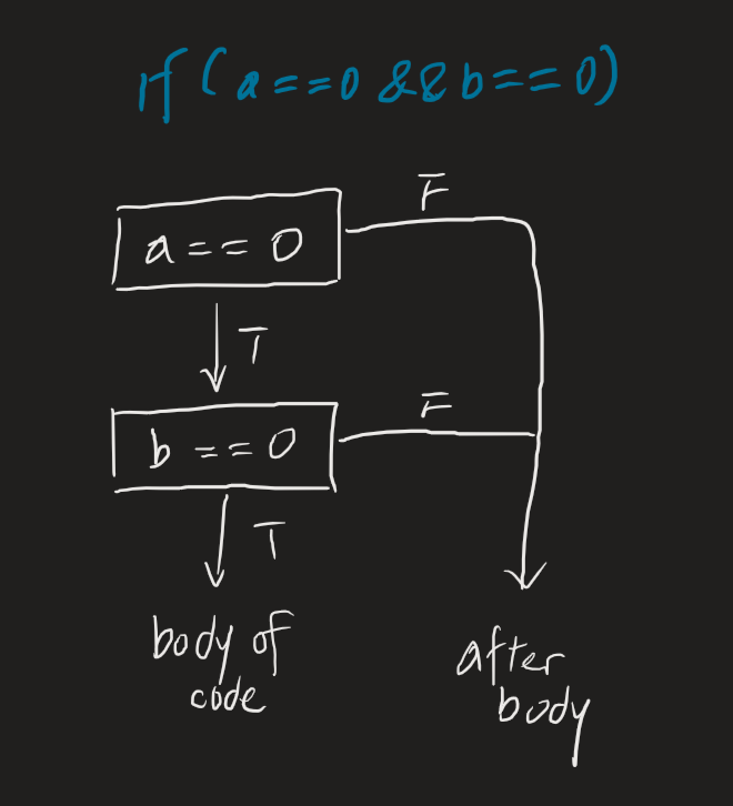
What about multiple conditions? i.e., a == 0 and b == 0. We essentially follow a modified control graph. Because we have AND, we can do a lazy evaluation; if the first statement is false the next doesn’t need to be evaluated.
See also
- Branch, a version control concept in software engineering