In digital systems, logic gates perform logic operations with multiple inputs and one output. Networks of gates are called logic circuits. All digital circuits can be written with some combination of NOT, AND, or OR gates.
Basic gates
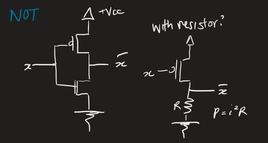
Gates are often represented with graphical symbols. Operations can be expressed through truth tables.
 The XOR gate (“exclusive-OR”) is associative, i.e., . For any odd number of 1s in a truth table row, XOR outputs a 1. For an even number, XOR outputs a 0. This implication is useful for full adders.
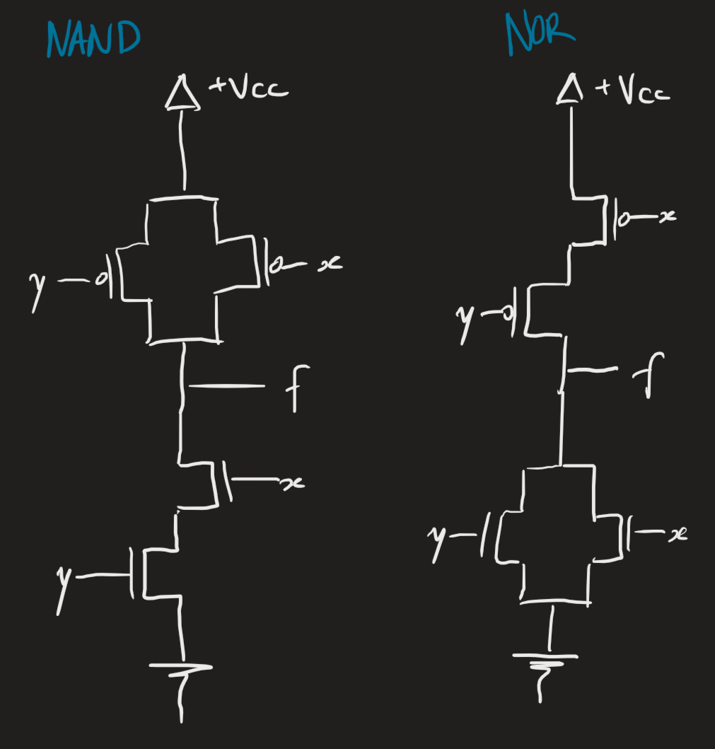
NAND and NOR gates are universal gates. Any digital circuit can be written with a combination of NAND/NOR gates.
Transistor equivalents
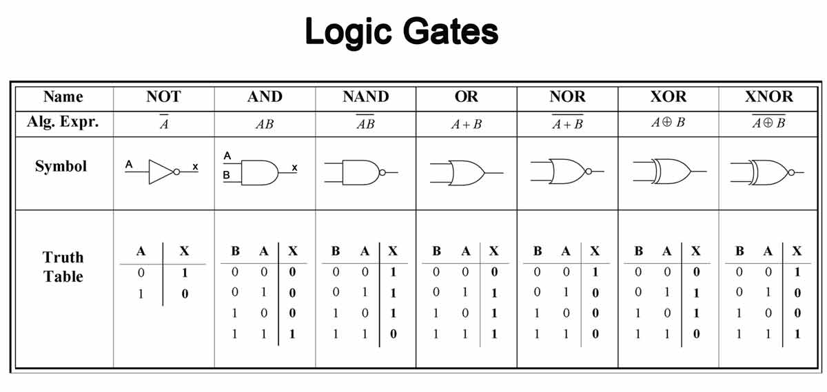
All logic gates are constructed with MOSFETs.
The NOT gate:1
 The NAND and NOR gates:
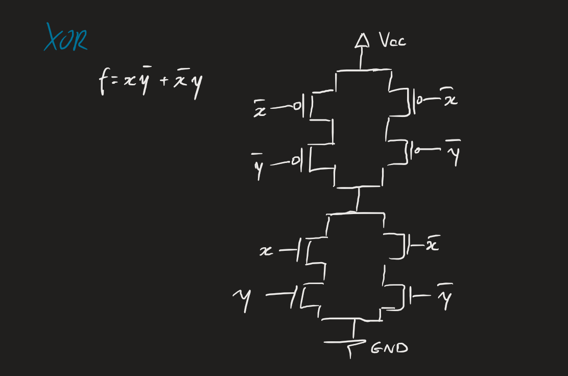
 An XOR gate:
Other equivalents
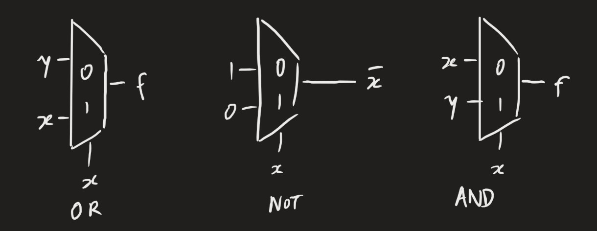
We can use multiplexers to represent OR, NOT, AND:
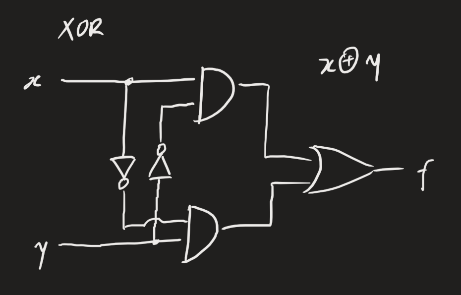
 Basic gates to implement the XOR gate:
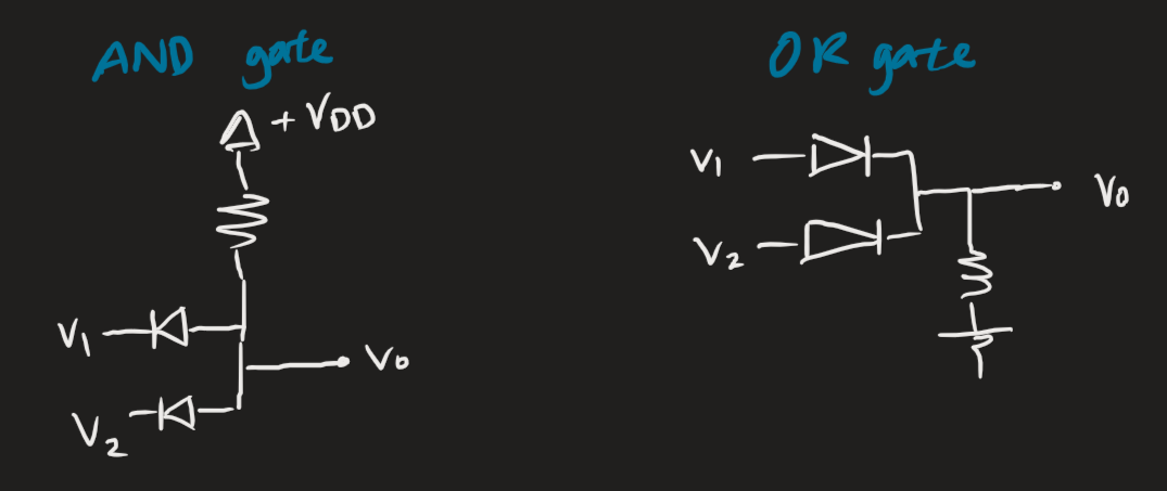
 We can use diodes to construct AND and OR gates are below. The idea with the AND gate is that for low inputs, the current from will split and flow in the diode branches. For a high input, the current will stop flowing through the diode. Then, for both high inputs, no current will flow through the diode branches and will flow out.