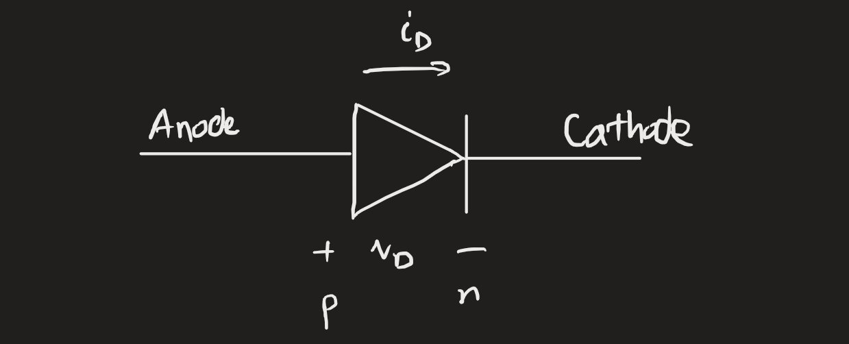
Diodes are non-linear circuit elements that conduct current only in the forward direction. They see considerable use in electronic circuits, especially rectifier circuits, protection circuits, and signal converters.
Ideal model
A highly idealised diode has an i-v characteristic with two distinct regions:
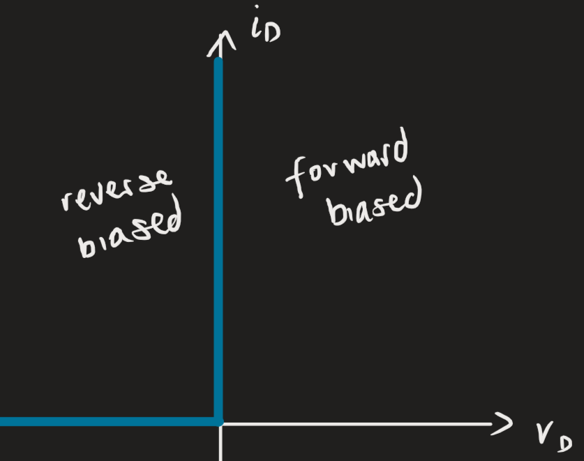 The reverse-biased region (diode in an “off” state) occurs if the voltage polarity of the diode is negative. No current will flow, but the voltage will be non-zero, i.e., we get an open circuit. In the forward-biased region (in an “on” state), where the voltage polarity is positive, current will flow fully forward with no impedance, i.e., we get a short circuit.
 Practically speaking, we need a resistor in series with the diode. Because , and the diode would melt or the power supply would trip a fuse.1
Circuit analysis
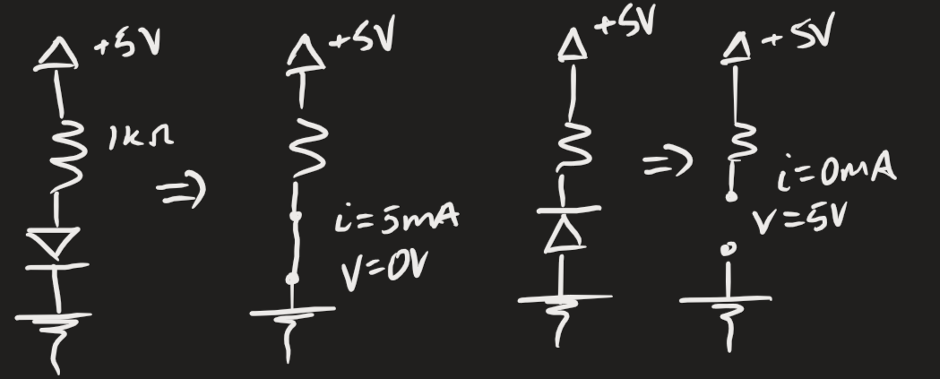
With multi-diode (ideal) circuits, we need to “guess” and “check for consistency”. For instance, we can start with guessing that all diodes are on, and seeing if the resulting current directions and voltage polarities are accurate. If not, we continue and calculate for one of them being on.
What does “check for consistency” mean?
- Find current across components, equate by KCL if they have a continuous branch.
- Find voltages across components; note the polarity of the node attached to the diode and check if it’s going to be consistent with the assumption (i.e., a positive polarity when we assumed the diode’s off means the guess is incorrect).
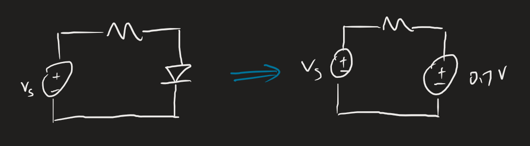
Constant voltage drop
The constant voltage drop model improves on the ideal model by being more accurate but still easy to use. Since real diodes have a current spike around 0.7 volts, we simply move the forward/reverse biased vertical line of the ideal model from 0 to 0.7 volts. Practically what this means is that we get a voltage drop of 0.7:
 Note that if , the model isn’t accurate anymore and we should use the iterative approach with the exponential model. This is because the diode still conducts below , and we lose that insight when we use this model.
Real exponential model
The diode equation is given by (excluding the Zener effect and breakdown voltage):
and we can easily derive the latter by re-arranging:
where:
- is the saturation/scale current (in the semiconductor and electronics fields ), sometimes the reverse saturation current since it’s in the reverse region. This depends on the physical dimensions of the semiconductor (bigger area, more current), and is temperature-sensitive (will double for every 5 degrees). Usually around .
- is a large constant; . For , . For , . The values are:
- is the Boltzmann’s constant; .
- is the absolute temperature in Kelvin, usually around 20 to 25 degrees Celsius.
- is the elementary charge, .
- And and are the current and voltage.
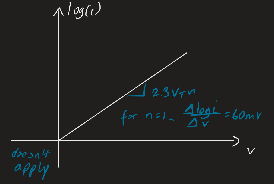
What if we have two different voltages in identical diodes? We get two different equations for current, which we can find the ratio for:
What we can interpret from this is that: a decade change in current is a change in diode voltage drop, or roughly . We can use a semilog plot:
 In the reverse-bias region, the exponential term becomes negligible:
Iteration
Analysis by iteration is the most accurate diode analysis technique. The idea is that we want accuracy and we also don’t necessarily know . We have two equations:
if the diode is in series with a power source and resistor. The intersection point of the graph is the operating point of the diode:2
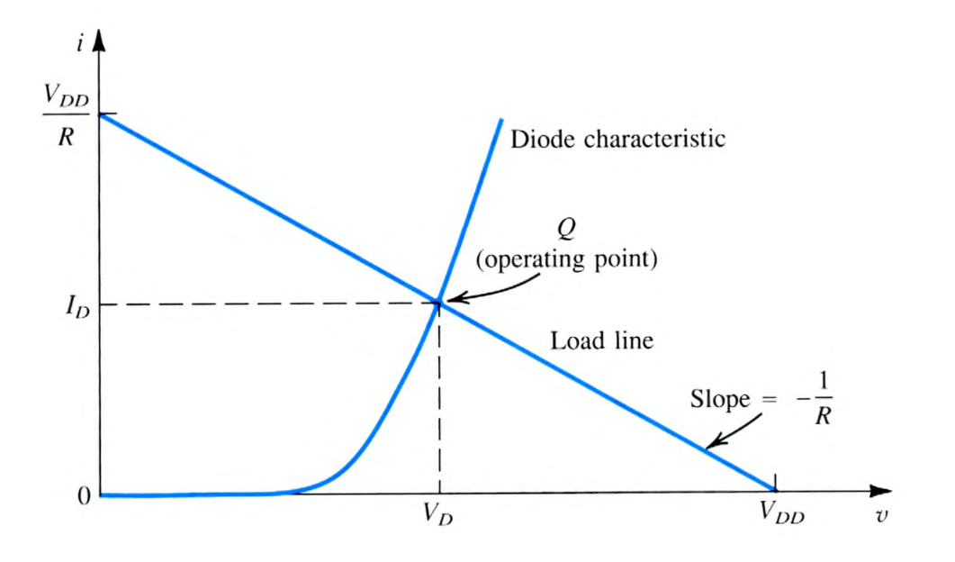 We can’t set the equations equal. It’ll never work because one term will always be inside a . For our analysis, we start by taking a guess for and substitute that into the linear KCL equation to get current (). Then, if we know one of the operating points, we can substitute it into the below for and :
And we solve for . We then rinse and repeat substituting the we found into the linear equation as and find and continue the iterations.
and are from the previous iteration (if at beginning, the initial point given). is computed from the KCL linear equation, is what we find; and are from the current iteration. When we go to the next iteration, the “current iteration” we just computed is now the previous iteration.
More iterations means more accuracy. But smaller changes with each iteration mean that there are diminishing returns each step so we should stop after the 2nd or 3rd iteration.
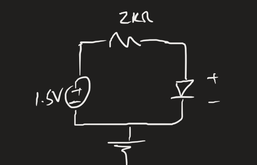
Example
Let’s take this circuit, assuming the diode operates at 0.7 V at 1 mA:
i.e., and are from the previous iteration. is from the current iteration.
Then:
Physics
Diodes use a pn junction, since it can conduct substantial forward current and almost no reverse current. The cross-sectional area is proportional to below; doubling the junction size will double the value of and hence the current through the diode.
The i-v characteristic is given by:
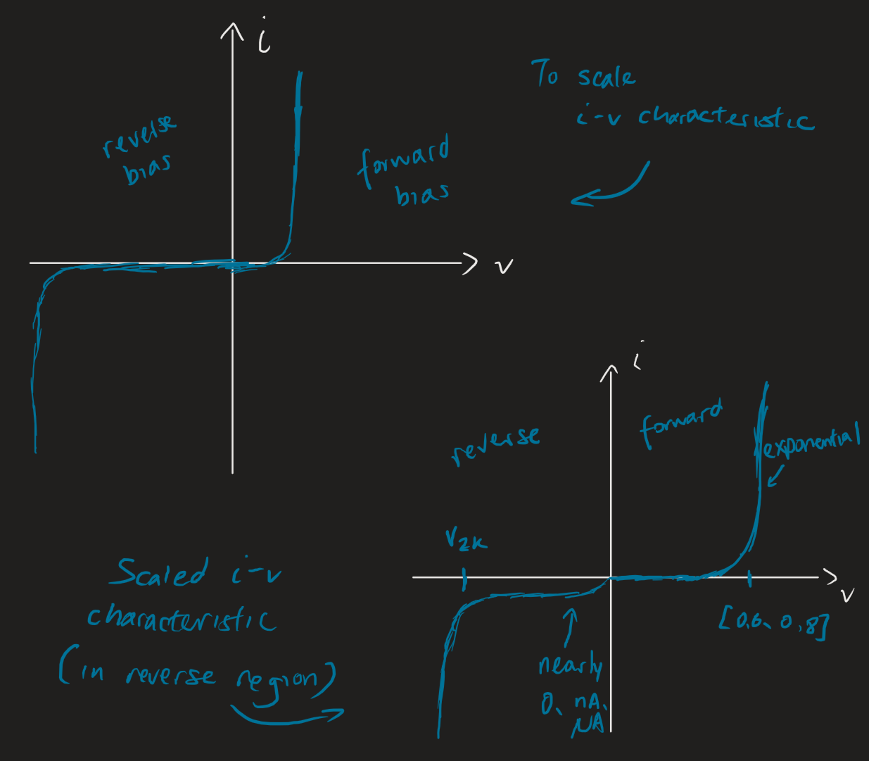 Some observations:
- The forward bias region is given by an exponential function. Why? I’d have to take a semiconductors course.
- The voltage where it begins to spike up depends, but is almost always between . A different value means “other things are happening in the device”.
- Pretty similar to the ideal model! Except not at 0.
- In the scaled plot, we observe that the current isn’t exactly zero — it’s very close, in the and range.
- In every diode there’s a sudden negative current that’s close to immediate. This is a “breakdown voltage” , like a breakthrough of current. Breakdown usually isn’t destructive as long as the power dissipated is limited. The heat could melt the device.
- It’s sometimes denoted . The stands for Zener diode and the for knee. Some more notes over there. In general, , but non-Zener diodes are around .
- Reverse breakdown is used in voltage regulation and light detection.
Diodes are also in general quite temperature sensitive (because semiconductors are):
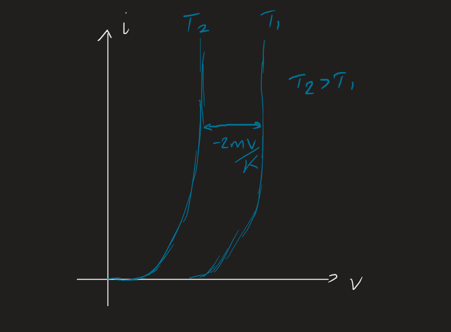 For every increase in degree (temperature), the voltage drop across the diode decreases by about . This has been exploited for use in electronic thermometers.
Addendums
The full diode equation is given by:
The differences between the above:
- is the diode ideality factor. For silicon, . Usually we just use 1.
- The exponential term tends to be HUGE. So we can usually ignore the term because it really doesn’t contribute much to the equation.
In electronic design, we pick for the proper operating point for forward conditions. The PIV (peak inverse voltage) is a property of the circuit: i.e., the max reverse voltage the diode will see in the circuit.
Applications
Diodes find key applications in: