In electronics, rectifier circuits are used to create an output signal with a DC value from an input signal that is purely AC. We implement these with diodes.
There are a few main types of rectifiers:
- Half-wave rectifier
- Full-wave rectifier
- Bridge rectifier
- Peak rectifier
Wave rectifiers
Half-wave
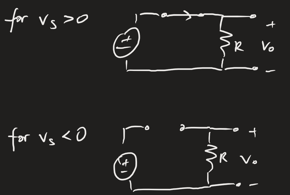
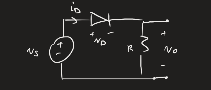 For instance, say we have an input signal , which is a purely AC signal (DC value is 0). Because of the unidirectional nature of the diode, we only conduct positive values of the input waveform.
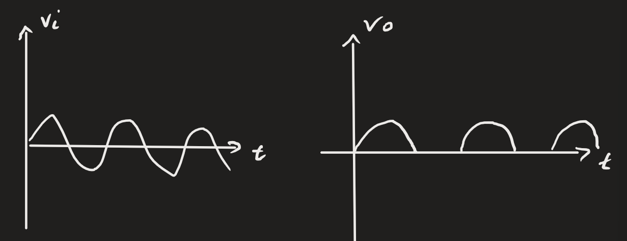
 Our resulting output waveform has no negative components, and has a DC component now. The output signal is called a rectified signal. If we follow the constant voltage drop model of 0.7 V, the rectified signal won’t exactly follow the input signal (it has to pass the threshold).
 Some extra considerations: for the negative part of the signal, does the diode reach breakdown? If it does, we need to choose another diode. What about if we use the real model instead of CVD? We should just toss it into SPICE instead of hand-computing it.
Full-wave
The premise with the full-wave rectifier is that it seems wasteful to lose the negative components of the signal. We use a transformer to induce a voltage in a circuit with a centre tap:
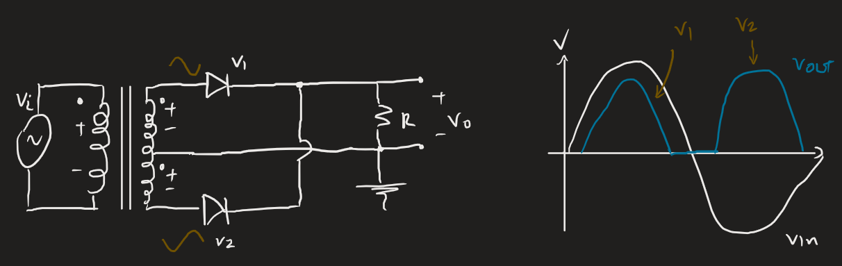 The idea is that there are two equal voltages with different polarities delivered to the diodes. While is positive, diode 1 will conduct but diode 2 won’t. While is negative, diode 2 will conduct and diode 1 won’t, producing the above. We essentially have conduction at all times.
Most rectifier applications use a full-wave. Note that we still have downtime because of threshold requirements.
Bridge rectifier
The bridge rectifier uses four diodes attached like below:
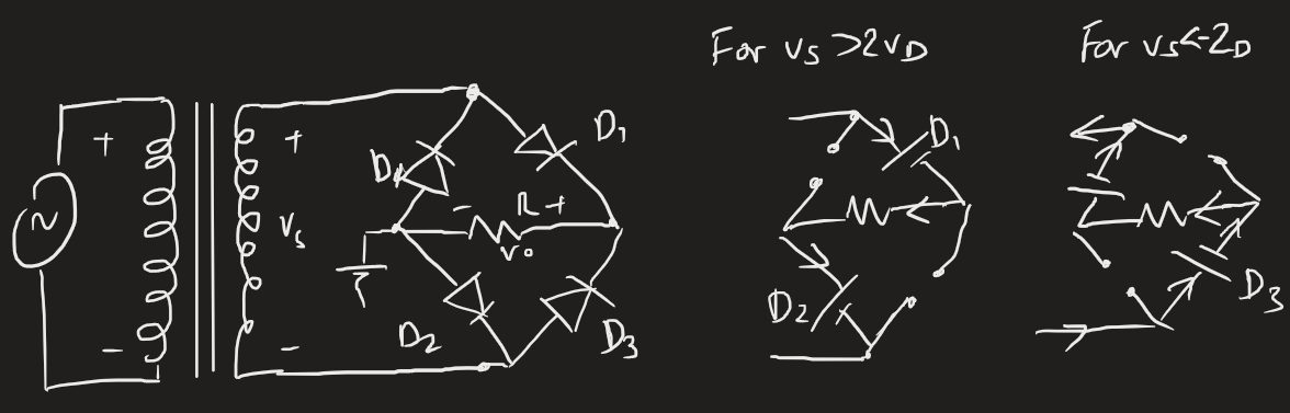 For positive , diodes 1/2 are on, while diodes 3/4 are off. Because of the nature of the voltage drop over , this also keeps and off. The opposite case keeps diodes 3/4 on.
This has the same output waveform as the full-wave rectifier. This comes down to the cost of diodes versus transformers. Diodes are cheap!
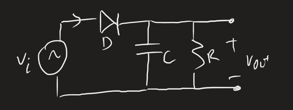
Peak rectifier
The peak rectifier is designed to store the peak value of . With an ideal diode, the capacitor will store charge following the input signal, then as goes negative, the capacitor has a greater polarity than , meaning the diode turns off and the capacitor is effectively isolated. It then dissipates some of that charge over the resistor. We usually use this circuit to detect the peaks in an input signal.
 A circuit with no resistor would hold the peak and have no drops. In practice, our load has a resistance, so this never occurs. We also design for a large time constant such that it approximates the no-resistor-circuit. With this, it’ll take a long time to discharge; worst case, a long delay also means a long charge-up time.
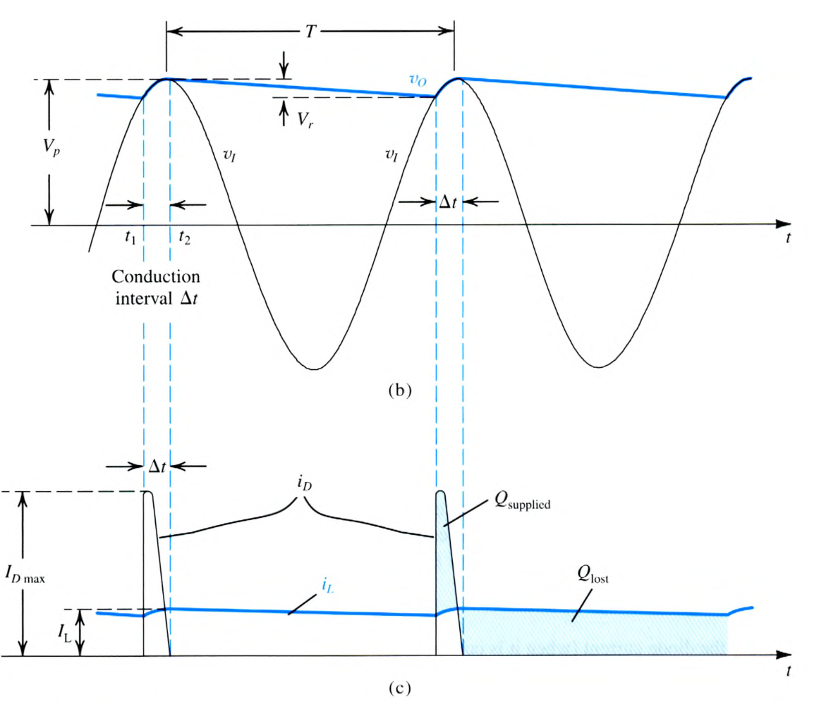
The difference between the lowest point and peak is called the “ripple”, a deviation from the resulting DC value. We design to minimise the ripple:
where is the peak voltage, is the frequency. We assume to get a small . will change the specific shape of the output waveforms. All of this serves to approximate a DC power supply pretty well!