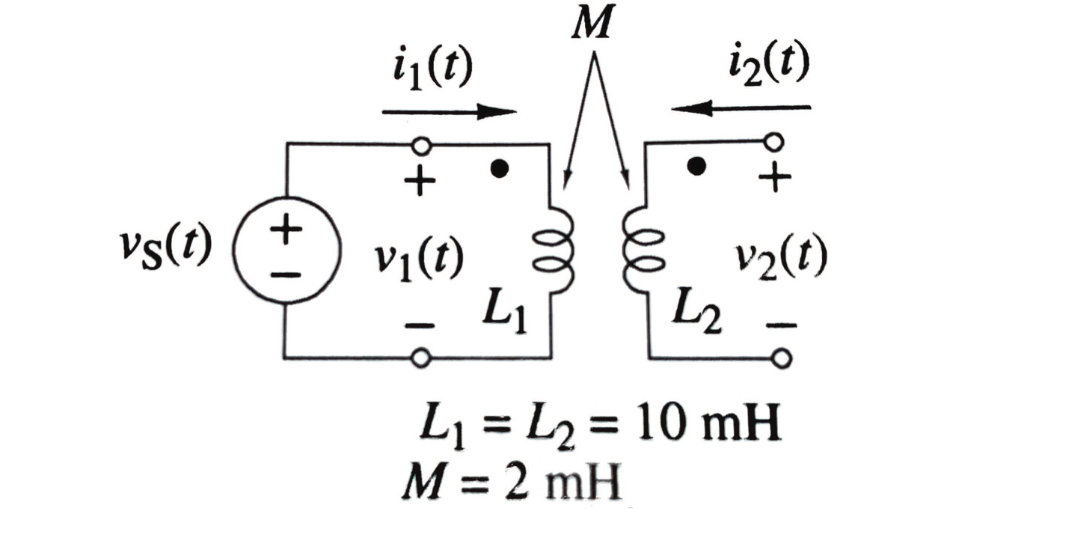
A transformer is a circuit component that transfers electrical energy from one circuit to another circuit (or multiple different circuits). It relies on the principle of mutual inductance (see that page for the dot convention).
Some important terminology moving forward:
- The coil connected to the source is called the primary winding, and the one connected to the load is called the secondary winding.
- We define the turns ratio, .
- If (), we have a step-up transformer for increasing voltage level. For (), we have a step-down transformer for decreasing voltage level. For , we have an isolation transformer.

Ideal model
We define the ideal transformer as consisting of two or more coupled coils wound together a linear magnetic core, with perfect coupling. We importantly assume that it has infinite permeability. The implication of this is that and . We also assume perfect coupling, where where . All of this avoids the need for ODEs in the real case.
From above, we can find the voltage ratio, given an additive or subtractive case:
and the current ratio. Here, is for the additive case (it is reversed from the voltage ratio).
Practical implications
When we look at this circuit, since the right circuit is open, we functionally get all terms as 0. When we end up solving for , we find that it’s a scaled replica of the input voltage (i.e., same frequency and phase, smaller amplitude), even though there’s no direct connection between the input and output circuits. These properties make transformers so useful in the power grid: isolation, replication, and scaling.
Theoretical case
The physical foundation behind transformers are explained by mutual inductance.
Transformer cores are often made of iron, which have a high relative permeability. Very little current can fully establish a magnetic field in the core — which we call the magnetising current creating a small magnetising flux.
The coupling coefficient for modern transformers is , which makes it useful for power grids, since we get a small/negligible drop in voltage.
See also
- Transformer, in deep learning