Nios II has a simple interface to interact with interrupts. On the hardware level, Nios has 32 wires for handshaking with equal priority for getting interrupts.
Registers
In Nios, we have six specialised registers for interrupts:[^1]
ctl0/statusreflects the operating status of interrupts. We use two bits:- Bit 0 is the processor interrupt-enable bit. When PIE = 1, external interrupts are accepted. When PIE = 0, they’re ignored.
- Bit 1 is the supervisor mode bit. See below for when we switch it.
- This is controlled by the operating system, not the users! When in user mode,
rdctlandwrctlcannot be executed. etandeaare only accessible in supervisor mode.
- This is controlled by the operating system, not the users! When in user mode,
- The rest of the bits are used when the MMU is used.
ctl1/estatusstores a copy of the status register during exception processing.- This is because during an interrupt,
ctl0is changed to ignore external interrupts.
- This is because during an interrupt,
ctl3/ienableis used to enable individual external interrupts. This is device-specific (the DE1-SoC has a few mapped ones).ctl4/ipendingis used to indicate which interrupts are pending. A given bit is set to 1 if the interrupt device is active and the corresponding bit inienableis also 1.
Nios also has two specialised instructions for reading and writing instructions to the control registers: rdctl and wrctl. These are executed only in supervisor mode.
Sequence of events
When the program enters an interrupt, the address of the next instruction to execute is stored in a special register (in Nios II, this is in ea/r29). The architecture may also specify a special return instruction to access the register (eret) when the interrupt handler is done.
Specifically in Nios II,
eawill store the instruction after the one that’s been interrupted, i.e.,pc+4. At the end of the exception handler, we should subtract the value ofea:subi ea, ea, 4.
There are several things we need to do to enable the ability to flag interrupts:
- Enable interrupts on the device side (often a flag or control register).
- On the
ctl3register, the individual device interrupts need to be enabled by writing. - Globally, interrupts must be enabled in
ctl0, so that the program will stop.
During an interrupt:
- The processor stops executing instructions. The below is all done by the hardware.
- The address of the next instruction to execute is stored in a special register. In Nios, this is in
ea/r29.pc + 4is written intoea. - The value of
ctl0is copied toctl1. - The PIE bit of
ctl0is set to 0, so that further interrupts are ignored. pcis set to the address of the exception handler. On Nios, it’s0x20.
- The address of the next instruction to execute is stored in a special register. In Nios, this is in
- The code for an interrupt request handler is executed.
- Any registers used within the handler must be saved on the stack.
- We need to determine where the interrupt is coming from. We do this by reading
ctl4and isolating specific bits.
- We do our thing. At the end of the IRH:
- The device needs to be told that the interrupt request was handled, i.e., edge bits must be reset in a PIT device.
- Machine states (registers, memory) must be restored, i.e., the stack must be popped.
- We need to subtract
eaby 4. This is because the previous instruction may not have been executed before being interrupted.
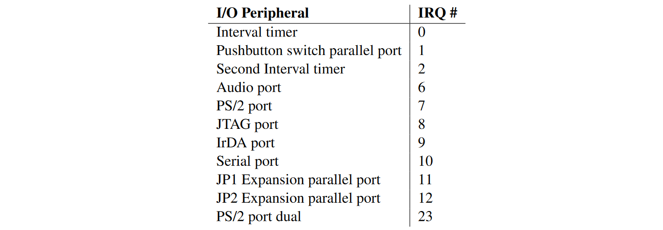
The specific bits to enable for the DE1-SoC in ctl3 are given below.
Exception handler
The exception handler is stored in a separate section of the Assembly code. By convention, it’s at 0x20 in Nios.
.section .exceptions, "ax"
.align 2
Any registers we use must be returned to the state they were at before. We store their values on the stack and pop them when done. The interrupt handler may be hardcoded in at a certain memory address, shared by all interrupt requests. Then software will probe which device requested the interrupt.
When we go into the interrupt handler, no other interrupts are checked, i.e., ctl0 temporarily ignores interrupts for the duration of the handler.
We also need to reset the interrupt bits in the devices. For instance, in the DE1-SoC buttons, the edge register must be reset.