Quartus Prime is a CAD tool that translates (or analogously compiles) hardware description languages onto a physical chip, like an FPGA. We can simulate in ModelSim.
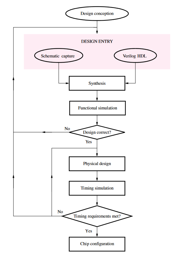
From an HDL file (like Verilog), Quartus will:
- Optimise any complicated logic expressions.
- Map Boolean equations to LUTs.
- Place LUTs into FPGA slots.
- Route and interconnect slots.
- Configure bitstream for LUTs and wires.
- Have a completed FPGA chip.
 Intel’s job descriptions describe Quartus as having several NP-hard algorithmic design and data analysis problems for potential software engineers to tackle.
Tools
The RTL Viewer is a useful tool to help us visualise the generated schematic and determine whether it matches what we intended. Make sure the project has been compiled, then go into Tools > Netlist Viewers > RTL Viewer. To visualise a sub-module, we can open a new tab and drop the module into the tab from the left sidebar.
Compilation
To compile files, we can load in (or create) a new Quartus project, specifying the proper top-level module and including necessary files. There shouldn’t be any duplicate modules between files.
If using a DE1-SoC, ensure that switch assignments are loaded in via Assignments > Import Assignments.
We can then compile via the pane on the bottom left. Double click Compile Design to compile. Any errors will show up on the bottom of the program. After compilation we can program the .sof output file to the FPGA. Open Tools > Programmer. Ensure the correct hardware is set up at the top (i.e., DE-SoC [USB-1]). Delete the existing device and press auto detect. For the DE boards, we use the second device.
Add the corresponding output file for the project in the File field for the second device. Tick Program/Configure, then press Start on the left to program onto the FPGA. By this point, any testing can be done on the physical board. For any problems, try re-watching this video.
Versioning
It looks like Standard and Lite editions are basically the same (just targeting different devices).