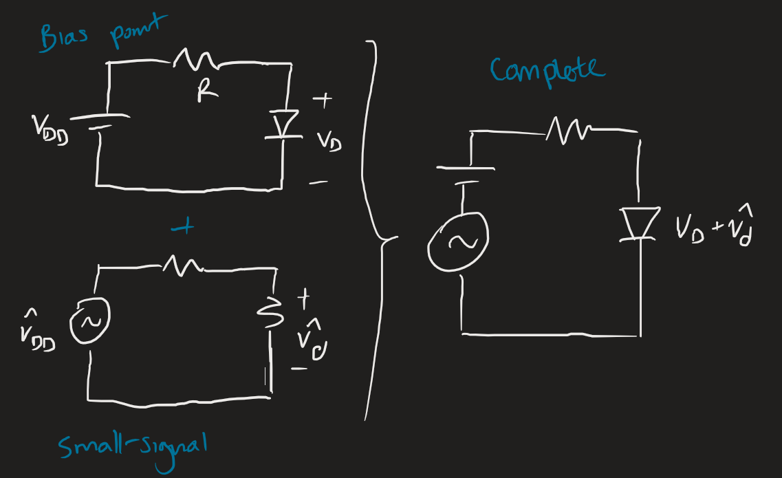
In electronics, we use small signal analysis to model non-linear behaviour in circuit components. Generally speaking we have the following equations:1
where is the total, is at the bias (or operating) point, is the small-signal (or incremental) value.
This analysis is only relevant if a small-signal condition is satisfied. The non-linearities of many devices mean that the input signal must be fairly small, otherwise we get some distortion and we lose the benefits of linearisation.
General steps
- Find the DC operating conditions.
- This means that capacitors are opened and inductors are shorted; and time-varying sources are ignored.
- Depending on the device, there are a few DC parameters to find:
- For a diode, we find .
- For a MOSFET, we find .
- For a BJT, we find at least one current value; if / isn’t given, we should find the other two as well.
- Use the DC operating conditions to find the small signal parameters. This will be specific to the device.
- For a diode, we find .
- For a MOSFET, we find , .
- For a BJT, we find , , . If we’re using the hybrid-π model, we need as well.
- Draw the small-signal circuit.
- Short DC voltage sources to ground, open DC current sources.
- Include capacitors and inductors now. If the schematic says (very large), we can short it.
- Solve the question. Typical question include:
- Gain:
- Impedance: and
- Design question: given a phase and magnitude of transfer functions at certain frequencies, what component values should we use?
Diodes
The small signal diode is modelled by a resistor:
We define as the DC voltage, as the DC current, as the thermal voltage. We also define as the actual signal, as the AC component of the signal, i.e., .
We usually want to use the iterative exponential model for the DC operating conditions. Not the constant voltage drop or ideal model. Small signal analysis is valid when variations in the diode voltage are kept smaller than about 5 mV.
MOSFETs
The MOSFET is modelled with a voltage-dependent current source, where is the MOSFET transconductance.
There are two equivalent models: the hybrid-π model and the T-model. The models for the NMOS and PMOS have no difference.
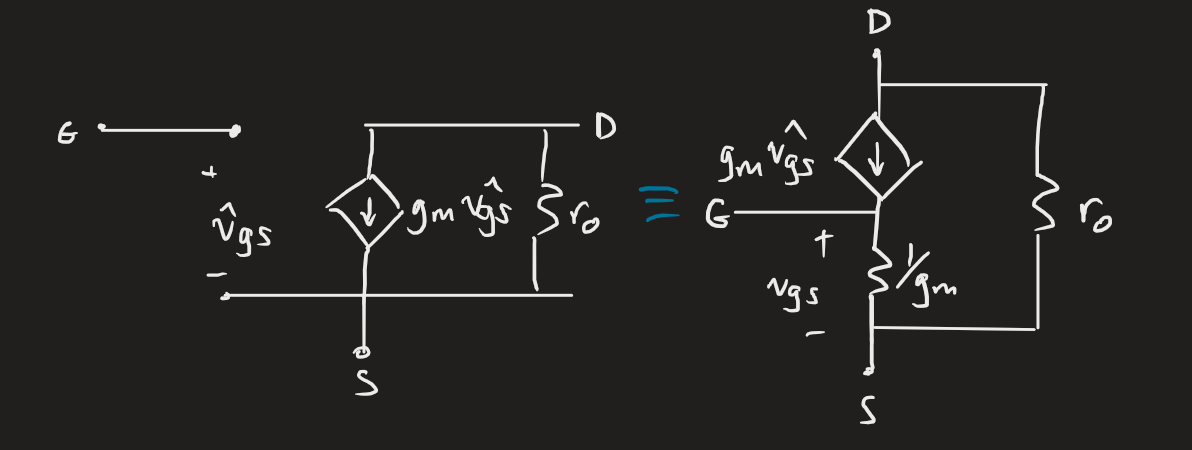 The applied signal is: . If we substitute this into our MOSFET saturation equation, we get:
where the first term is the DC bias current, and the third term is non-linear distortion (which we don’t want). This means that the small-signal condition is satisfied if the AC term is much smaller than the purely DC term.
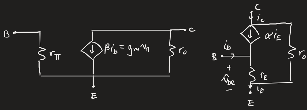
BJTs
Four key parameters. The transconductance is given by:
The base resistance is given by:
The emitter resistance is given by:
The output resistance due to the Early effect is:
Like the MOSFET, the BJT also has two small-signal models (with similar names). There’s no difference between the npn and pnp models.
Footnotes
-
The notation clusterfuck is (to the surprise of no one) pretty bad. I use a hat to denote the AC term, to distinguish between everything (and to bring it back in line with small signal analysis taught in MAT291 — Calculus III). ↩