First-order transient circuits are circuits with a resistor and one dynamic storage element, like a capacitor (RC circuit) or an inductor (RL circuit). We represent the governing equation as a first-order ODE.
As systems, RC/RL circuits are linear time-invariant, causal, and BIBO stable. RC circuits function as a low-pass filter, while RL circuits function as a high-pass filter. Because these systems have a single time constant, we also call RC/RL circuits single time-constant networks.
Circuits with a combination of inductors and capacitors are RLC circuits (second-order transient circuits).
The premise
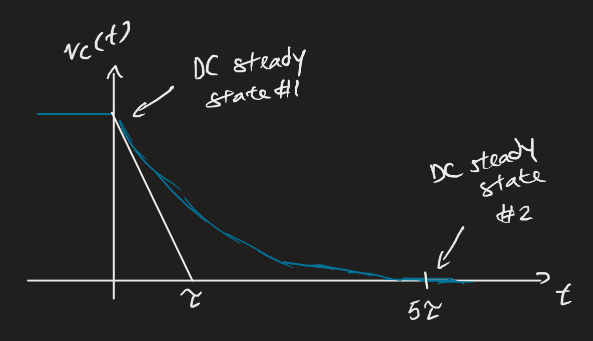
The idea is that first-order circuits will switch from one state to another.
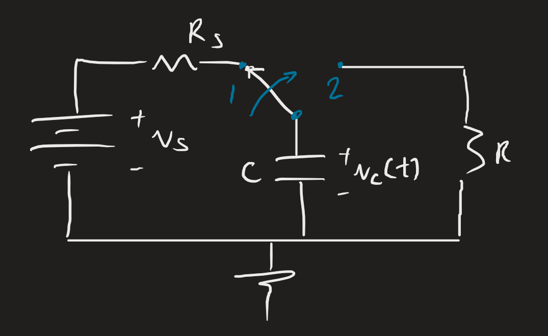
Our principle, which will be useful later, is that stored energy cannot be fully charged or discharged instantaneously.
 Our circuit will give us a first-order ODE. Note that we have a particular solution (or forced response) and a complementary solution (or natural response).
Solutions and analysis
We take a six step approach to solving first-order transient circuits. We jump straight to the idea without understanding how we really get from the ODE to the below:
- We assume that the solution for the or is of the form .
- We then assume that the original circuit has reached steady state already. We redraw the circuit where the capacitor is an open circuit and the inductor is a short circuit; we solve for the voltage across the capacitor or the current through the inductor at before the switch.
- Since the value can’t discharge or charge fully in zero time, we assume: . We replace the capacitor with a corresponding voltage source and an inductor with a current source.
- We then solve for , where since the circuits are mostly equivalent.
- Then, we find the time constant by forming a Thévenin equivalent circuit at the terminals of the storage element.
- For a capacitor, .
- For an inductor, .
- Then we put our solution together, :