The time response of a system is how it performs in the time domain. We can often infer key characteristics of the system from the transfer function in the Laplace domain, especially its zeroes and poles.
Pole interpretations
In general, the transfer functions we’re interested in either have real poles (i.e., a real multiple of 1) or a pair of complex conjugate poles.
Real poles
For real poles for a function , the pole is at . Then:
- For , we have a unit step times a function.
- For , we have an exponentially decaying function.
- For , we have an exponentially growing function.
Complex poles
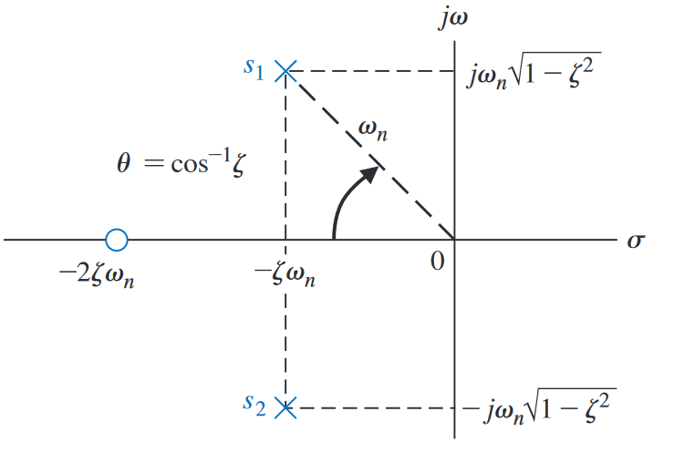
For complex conjugate poles in the form of , we define the natural frequency:
And the damping ratio (dimensionless):
And some extra formulas:
The relationship between everything is given by:1
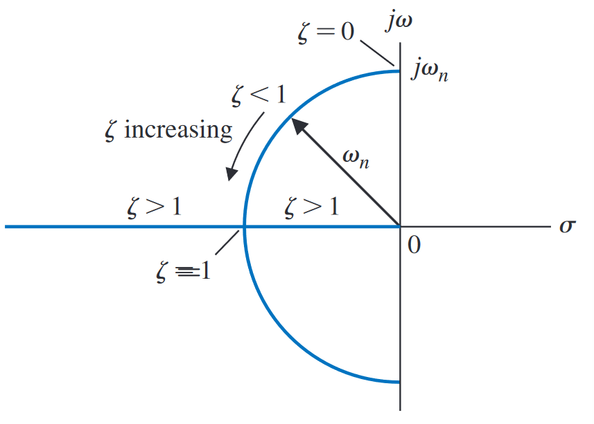
 And the magnitude of determines the location of the pole in the plane.1
 The time domain expression for a second-order ODE with characteristic polynomial gives us:
With a second-order transfer function:
These parameters are fortunately very interpretable. The closer to 0 the damping ratio, the more prone to and stronger the oscillations.
- : underdamped. Complex roots.
- : critically damped. Repeated real roots.
- : overdamped. Distinct real roots.
The poles of the transfer function are also interpretable:
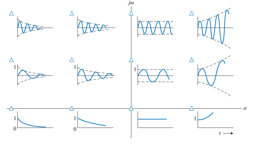
- For , we have a pair of complex conjugate poles with zeroed real parts. In this case, it just oscillates. Poles with a greater magnitude oscillate faster, i.e., poles further from the -axis.
- For a pair of poles in the RHP, we have an unstable system growing exponentially. If the imaginary part is zero, there’s no oscillatory part.
- For a pair of poles in the LHP, we have a stable system decaying exponentially. The further left the pole, the faster it decays.
This table shows the approximate time response given certain pole locations.1 Assume that if the imaginary part is non-zero that there’s a complex conjugate. The plots show the results for a second-order system.
 For transient systems (like the ones in the diagram), there are additional parameters that we design for. These help us control the behaviour of our system further.