Comparators compare two voltage signals and identify which of them have the higher voltage.
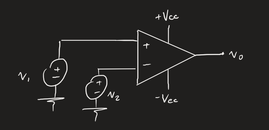
A natural candidate involves op amps, since by nature they have supply rails as an upper or lower bound. We assume they operate in saturation mode (i.e., not in linear mode), so that:
- If , then .
- If , then .
Observe from the diagram that this is basically just inputting into the op amp. Our only deviation from usual op amp circuits is that it operates in saturation mode.
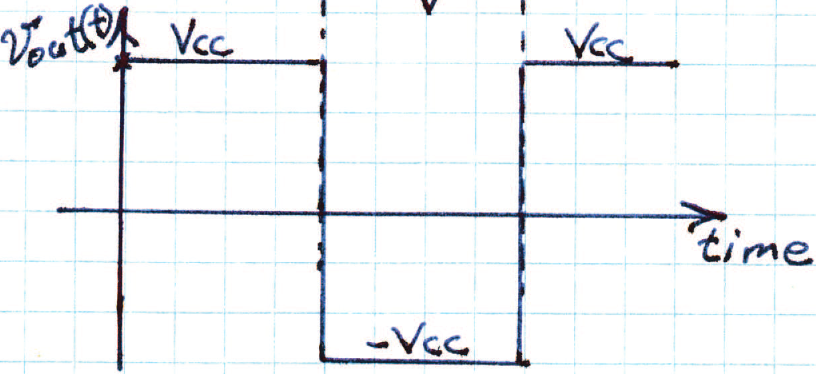
 An application of op amp comparators are in outputting square and triangle waves. We can set one signal to 0 and take in some other signal. From the rules above, we can roughly create a square wave where it goes peak-to-peak from to . To create a triangle wave, we’d need a capacitor somewhere in the circuit, since they don’t charge and discharge instantaneously.