Structural members (i.e., beams) have internal loadings and forces that we must consider in analysis.
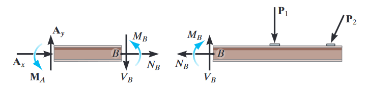 We refer to the component that acts perpendicular to the cross section as the normal force (also called the axial force), the component that acts tangent to the cross section as the shear force, and the couple moment as the bending moment. We can represent the variation of these internal forces and moments in internal force diagrams.
We generally use a sign convention for these loadings. A positive normal force causes tension, a positive shear force will cause a clockwise rotation, and a positive bending moment will bend the segment in a concave up direction (I like to think of this as a happy face).
In our exploration in CIV100, we focused on axial force diagrams (for horizontal forces), shear force diagrams (for vertical forces), and bending moment diagrams. Recall that in our analysis in statics we treat objects in equilibrium.
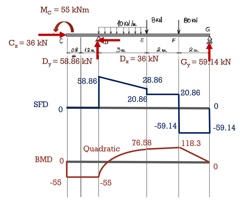
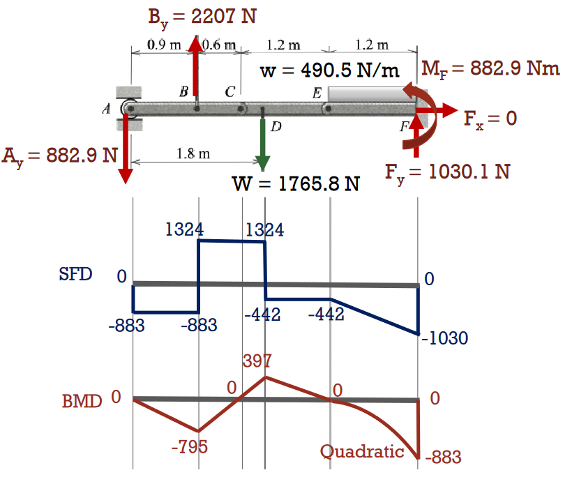
Examples
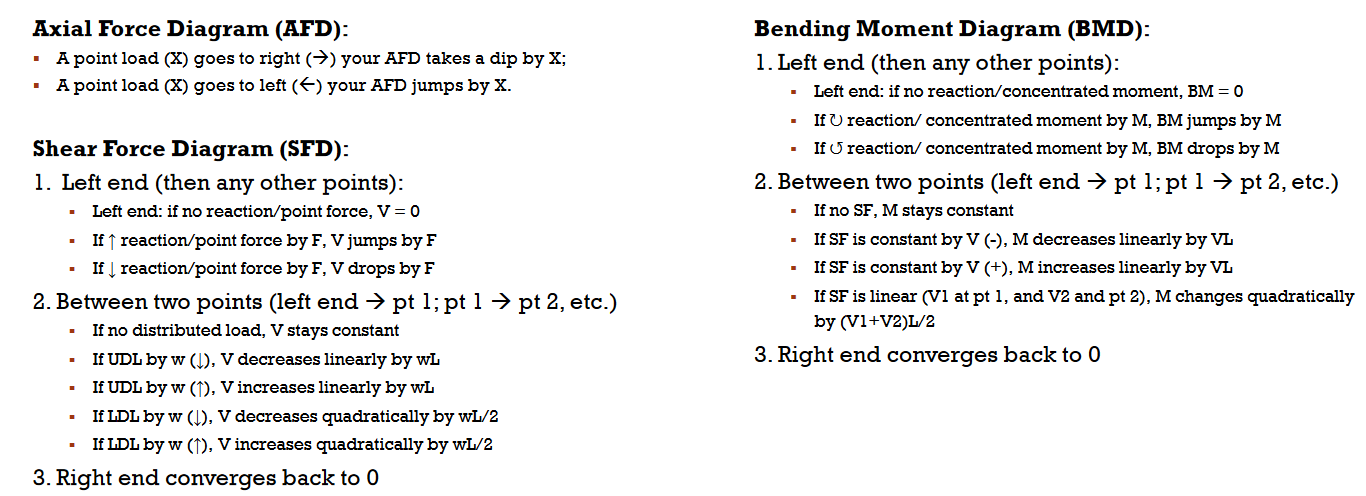
Ten golden rules
These rules largely trivialise much of the complexity in drawing internal force diagrams, and are good to follow whenever we conduct analysis. Note how the bending moment diagram is the integral of the shear force diagram.
- The bending moment is zero at the ends of a beam, unless any of the ends are fixed or an external moment is applied at the ends. At an internal pin in the beam, the bending moment is also zero.
- A uniformly-distributed load acting between two points along a beam will cause a linear shear force diagram and a quadratic bending moment diagram between those two points.
- If a linearly-distributed load acts between the two points, the shear force is quadratic and bending moment cubic between those two points.
- The change in shear force between two points along a beam equals the negative area under the distributed load acting on the beam.
- The slope of the shear force diagram equals the negative of the distributed force acting on the beam.
- The change in bending moment between two points along a beam equals the area under the shear force diagram.
- The derivative of the bending moment diagram is equal to the shear force.
- At points where the shear force is zero, the bending moment is at a maxima or minima.
- Concentrated point forces produce jumps in the shear force diagrams and kinks in the bending moment diagrams.
- Concentrated moments produce jumps in the bending moment diagrams, with no influence on the shear force diagrams.
The mathematics
We didn’t really focus on this in CIV100 — since you can mostly eyeball simpler diagrams. We define as the shear force, as the distributed load intensity, as the bending moment. Observe that these relations are fully consistent with our golden rules above.